Oculus2 Controller Firmware: Layout
Intro
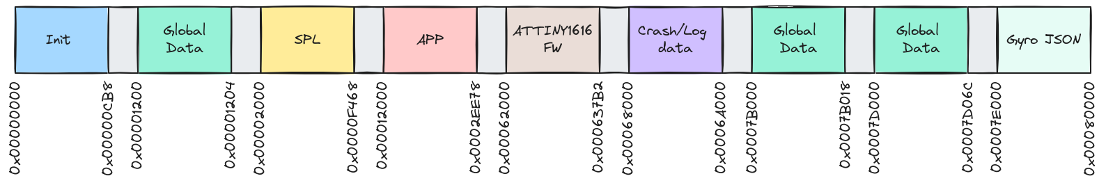
The extracted firmware dump provided an opportunity to better understand the memory architecture and data management within the controller’s firmware. The illustration below showcases the layout, and here’s a breakdown of the sections involved.
Memory Layout Breakdown
The firmware appears to be divided into several distinct sections, each allocated a specific memory range:
- 0x00000000 – Init FW
- This segment is responsible for initializing the controller’s hardware components and preparing the system for further execution. The controller perform basic checks, prepare peripherals, and execute essential routines before booting into the main logic.
- 0x00001200 – Global Data
- A section where global Unlock Magic and Device Lock Flag are likely stored. This data remains available throughout the runtime of the firmware.
- 0x00002000 – SPL (Secondary Program Loader?) FW
- This section contains the SPL, a critical component responsible for loading the main application. Its contents are cryptographically verified by the “Init” firmware. Additionally, the SPL offers access to the “Oculus FW Console” if the correct key combination is pressed during boot
- 0x00012000 – APP (Main Application) FW
- The main firmware is located here, containing the core application section responsible for the Oculus controller’s behavior. This area manages button inputs, haptics control, OTA and interaction logic. Its contents are cryptographically verified by the “SPL” firmware.
- 0x00062000 – ATTINY1616 FW
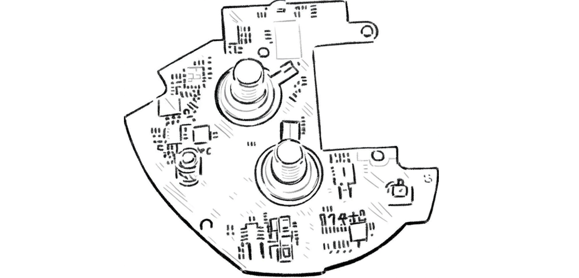
- The ATTINY1616 microcontroller appears to be part of the Oculus controller hardware, handling specific tasks such as sensor management and/or buttons control. This section holds its firmware, suggesting that some responsibilities are offloaded to this additional microcontroller.
- 0x00068000 – Crash/Log Data
- This section is likely reserved for logging crashes and other debugging data. In the event of an unexpected occurrence, such as a firmware fault or system error, relevant information is recorded here to assist in diagnosing failures. Additionally, this data will likely be sent to the Oculus headset and then uploaded to a server for further analysis.
- 0x0007B000 – Global Data
- A second global data section stores extra configuration details, including the “serial number” and other flags that need to be persistently accessed during runtime.
- 0x0007D000 – Global Data
- The third global data section holds initialization data for components like ADC, CAPTOUCH, and LED UX.
- 0x0007D06C – Gyro JSON
- This section stores sensor configuration data in a structured JSON format. Given the Oculus controller’s reliance on gyroscopic data for tracking motion, this data is likely critical for configuring the controller’s motion sensors.
Understanding the Layout
The segmented structure gives us a glimpse into the complexity of the Oculus controller firmware. Each segment plays a crucial role in ensuring the controller functions seamlessly with the Oculus VR system, handling everything from system initialization, sensor management, motion tracking, and error logging. Both the SPL and APP have their own vector tables, which are initialized during their respective startup processes.
What’s particularly intriguing is the ATTINY1616 FW section, indicating that the Oculus Quest 2 controller employs a co-processor for specific tasks, possibly for real-time sensor management.
FW header format
The SPL, APP, and ATTINY1616 firmwares each have a header preceding their main body, which can be used for identifying and verifying the firmware.
FW Header
| offset | size | desc |
|---|---|---|
| 0x0 | 4 | header magic |
| 0x4 | 4 | CRC |
| 0x8 | 4 | offset or header size |
| 0xc | 4 | payload magic |
| 0x10 | 4 | size |
| 0x14 | 4 | ?unknown? (0x02 is all cases) |
| 0x18 | 4 | vector table address |
| 0x1c | 4 | version/revision |
| 0x20 | 14 | ?_name_or_sn |
FW Magic
| type | magic |
|---|---|
| FW Header | 0x48654164 |
| SPL payload | 0x11223344 |
| APP payload | 0x01020304 |
| ATTINY1616 payload | 0xCAB70Ec4 |
Init layout
| start | end | size | desc |
|---|---|---|---|
| 0x0 | 0x1ff | 0x200 | vector table |
| 0x200 | 0xc27 | 0xA28 | .text |
| 0xc28 | 0xcb7 | 0x90 | .data |
SPL layout
| start | end | size | desc |
|---|---|---|---|
| 0x2000 | 0x202d | 0x2E | FW HEADER |
| 0x202e | 0x20ff | 0xD2 | empty area |
| 0x2100 | 0x22ff | 0x200 | spl vector table |
| 0x2300 | 0xd883 | 0xB584 | .text SPL |
| 0xd884 | 0xf467 | 0x1BE4 | .data SPL |
| 0xf468 | 0x11fff | 0x2B98 | 0xFF area |
APP layout
| start | end | size | desc |
|---|---|---|---|
| 0x12000 | 0x1202d | 0x2E | FW HEADER |
| 0x1202e | 0x120ff | 0xD2 | empty area |
| 0x12100 | 0x122ff | 0x200 | APP vector table |
| 0x12300 | 0x2a54f | 0x18250 | .text APP |
| 0x2a550 | 0x2ee37 | 0x48E8 | .data APP |
| 0x2ee38 | 0x2ee77 | 0x40 | app signature |
| 0x2ee78 | 0x61fff | 0x33188 | 0xFF area |
Next Steps
With this layout mapped out, the next step would be to dive deeper into each section and decode its contents. This involves:
- Analyzing the APP section to uncover the main application logic, which likely includes interaction handling between the controller and the VR system.
- Decoding the Crash/Log Data to understand the types of errors that can occur and how the firmware handles them.
This breakdown provides a stepping stone into further exploration and reverse engineering, shedding light on how the Oculus Quest 2 controller’s firmware is organized and operates.